Visualizzazione post con etichetta fotografia. Mostra tutti i post

venerdì 8 novembre 2013

The Gianluigi Perrella's World.

The Gianluigi Perrella's World.
Gian Luigi Perrella aka Menteblu61 on Flickr community, is a middle age man, employed for years in telecommunication companies, he worked in the past in electronic laboratories. Since he was a child, he was passionate of electronics, robotics projects and photography. 


“When you're curious, you find lots of interesting things to do.” ~Walt Disney

The GLP World


                                http://www.glperrella.it/http://www.glperrella.it/

Inside the site you can find topics regarding Photography, Hi Tech, Electronics Projects, Amenities.
Bookmark this QRcode: http://www.glperrella.it/
                                                        QR Code

venerdì 29 marzo 2013

Help Remshoot 3.0 become a reality!

The Project Remshoot 3.0

    Our project was initially designed to control few digital cameras as Nikon D50, but it can control many other digital cameras (our focus will be on Nikon and Canon DSLR and Coolpix or Powershot compact series) using the PTP standard, everything depends on the specific functions provided by the camera you own.
Once connected to the USB port on the camera, with the function of discovery capabilities, Remote Shooter 3.0 knows which commands and properties are available. For limited features as Focus&Release combined with Time Lapse, a stereo jack 2.5 port is available. Just buy a cable suitable for your remote control port specific for your camera.
Our goal is selling an flexible, upgradable and open Camera Control, for appassionate and professional at lower price possible!

Main features:
  • Remote Shoot;
  • Time Lapse (interval in sec,repeatition);
  • Shutter Speed Settings;
  • Aperture Settings;
  • Iso Settings;
  • Bracketing on/off;
  • Shake&Shoot (using your android phone accelerometer);
  • Sound&Shoot (adjustable level using your android phone mic);
  • Read&Shoot (programmable actions by a simple scripting language)
  • Thumbnail on app of the last shoot
  • USB PTP mode connection for full control (depends on camera)
  • Jack port 2.5mm for simple focus and release control
  • I/O port expansion for external sensor/actuator (eg light sensor or flash,may need a board interface)
  • Wireless firmware Upgrade (many other features on plan)
  • Li-Po Battery rechargeable from any phone microusb power supply
The app on Android or Windows PC, is released in OpenSource, radically extending the usability of the device.
With a language of simple and intuitive controls, you can control your camera.
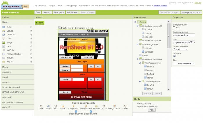
We use Google App Inventor for Android to create the GUI editable by anyone, so it will be easy to implement custom functions so far unthinkable.
If you have no programming skills, you can write a sequence of commands to a text file, click a button on your smartphone and will be read and executed by the application.
PTP Command.txt
//Script to activate Time-Lapse ,
100 shots, one every 30 seconds

TIMERIP=100.       Set number of shot
TIMEINT=30.         Set interval between shot, in seconds
ENTIMER=1.          Enable Time Lapse

video


Presentation
 Technicality for geeks! :-)
Processor                             PIC24FJ64GB002 16BIT, USB-OTG 8K Ram,16Mips@32Mhz
Program Memory                  64K Flash
Communication                    Bluetooth serial module class2 certified 30ft/10mt coverage
Power supply                        3,7V 750mAh LiPo onboard battery
Size                                    60 x 60 x 25 mm, 50 grams
 
Firmware tested so far on:
Nikon D50 (full features, see video)
Nikon Coolpix AW100
Canon Powershot A300
Canon Poweshot S500

Remote Shooter 3.0 assembledRemote Shooter 3.0 finished

What We Need & What You Get


Hello guys, we Need €16,500 to make RemShoot 3.0 project become reality!
With your help, we'll raise the €16,500 that we need to:
Get the boards CE certified – Regrettably, In Italy this is an expensive process for the certification lab to give us the ability to distribute the product.
Produce the first run of boards – In the past we've been prototyping previous versions through very small but expensive batches of boards.
Develop and test compatibility over a wide range of Digital Cameras (as many possible, but at the beginning our primary goal will be on Nikon and Canon DSLR or Coolpix and PowerShot compact series) 
Today we plan to develop mainly on:
Canon EOS 30D,EOS 40D,EOS 60D,EOS 400D,EOS 450D,EOS 500D,EOS 550D, PowerShot SX220 HS
Nikon D50,D60,D70,D90,D300,D700,D5000,D5100,D7000,Coolpix 7900
If you decide to contribute, please specify which digital camera you have.
After the previous versions based on our Pic-Ap-Board, (that hardware was thought for a wide variety of applications, not only for photography),  we're now reached enough knowledge and ready for starting this new project, RemShoot 3.0. But, the only way to make RemShoot 3.0 reasonably priced for everybody, is to do a reasonable volume production run of the boards. So in our budget plan, €16,500 is the minimum amount we need for Certification, assembly and manufacture of the first run of boards, including rechargeable  LI-PO batteries and the self made resin enclosure box.
If you are a fan of Creative Photography and HI-Tech, we toughly recommend the RemShoot 3.0 Limited Edition at €75 each (Italy shipping included; add 15 euro for International shipping).
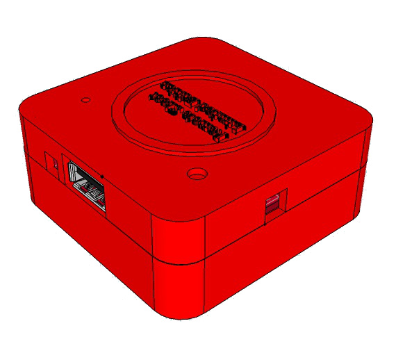
With this Kit, you'll get a finished product in a resin, original enclosure box, in one of 4 color at your choice (Red, Black, Blue or Yellow), the board fully tested and programmed with the latest firmware available. Each RemShoot 3.0 kit contains  moreover a rechargeable LiPo battery, with it’s dedicated micro USB port for charging, 1 Bluetooth module to wireless interact with the application on Android devices or a PC running Windows S.O, the app RemShoot for Android, (including source code) , the customized Pc Windows tool to easily upgrading via Bluetooth the board.
Last but not least, we plan to make several upgrades and implement other features to enrich RemShoot 3.0 Project, so it’s wireless firmware upgradable from a PC Windows  via Bluetooth. You can free your creativity with RemShoot 3.0
Developer


To make RemShoot 3.0 a reality, go to the crowdfunding Indiegogo campaign http://igg.me/at/remshoot30


Impact

You can become one of those people who gave love for creating the best upgradable, flexible and open camera controller . Help us to free your creativity!

Became an actor of this project and let's become RemShoot 3.0 a reality!


FAQ
Italy shipping included; + 15 for International shipping
For International Shipping  you'll need to add an extra 15. How do you add this money? When you select a contribution level, you'll be prompted to enter the total contribution amount just below. Add the 15 to the cost of the reward there. eg second batch november'13 of RemShoot Limited Edition:  75+15= 90
What if I forgot to add the 15 for international shipping?
After the project is funded and we're ready to ship, we'll contact each contributor to confirm shipping details. If you didn't add shipping when you contributed, you can add it then.
 RemShootSupporter gift sample photo:
RemShoot Supporter

lunedì 21 maggio 2012

Remote Shooter BT 1.0: Controllo Bluetooth di macchine fotografiche per Android

main foto2
Dopo la realizzazione di Remote Shooter 1.0, la soluzione per il controllo remoto dello scatto di macchine fotografiche digitali con funzioni di Time Lapse e ad eventi, trasferiamo l'interfaccia grafica e le sue funzioni su dispositivi Android utilizzando App Inventor.

NEW:
Testato su:
Nikon Coolpix  AW100
Nikon D50
Canon Powershot A300
Canon Poweshot S500
L'idea nasce dalla curiosità di sperimentare su Android con App Inventor e dalla necessità pratica di espandere l'interfaccia grafica del Remote Shooter 1.0 per rendere al contempo più semplice e rapido l'inserimento dei parametri di Time Lapse o di future funzioni allo studio.
Nel caso infatti sia necessario inserire grandi intervalli di tempo o numero di scatti, ci siamo resi conto che poteva essere complicato e forse anche tedioso, usare solo i tasti up/down sulla board.
Per chi non conoscesse il progetto Remote Shooter 1.0, è sostanzialmente un sofisticato telecomando per lo scatto remoto (ma non solo) di macchine fotografiche digitali tramite la porta USB, molti modelli infatti di compatte e  DSLR, Nikon e Canon ad esempio, sono compatibili in PTP mode con la scheda USB PIC-AP-BOARD (PIC Auto Programming Board) ed il firmware RemShoot 1.0 (Remote Shooter).
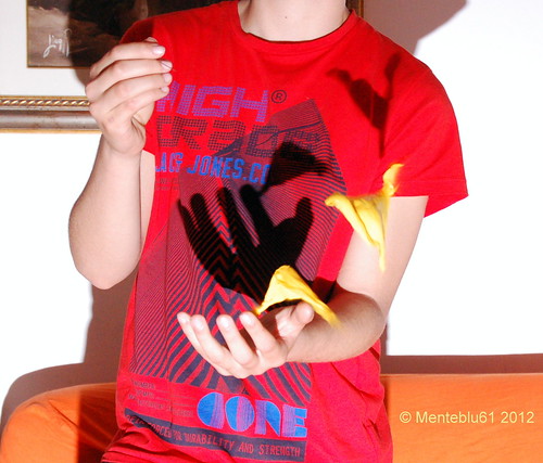
La possibilità di attivare remotamente molte funzioni (prima di tutto lo scatto) sulle macchine fotografiche digitali, rende possibile realizzare fotografie a volte impossibili o almeno difficili da realizzare con il metodo tradizionale a causa dei tempi di reazione umani.
Il protocollo PTP e applicazioni nella fotografia.
Gran parte delle macchine fotografiche digitali di fascia medio alta mettono a disposizione un set di comandi PTP per il loro controllo remoto, o semplicemente per il trasferimento delle immagini su un pc.
Utilizzando gli opportuni comandi e proprietà l’appassionato di fotografia potrà:
1) Remotizzare il pulsante di scatto (shutter),
2) Realizzare un Intervallometro (Time Lapse)
3) Scattare foto automatiche sulla base di eventi rilevati da sensori di luce e suono.
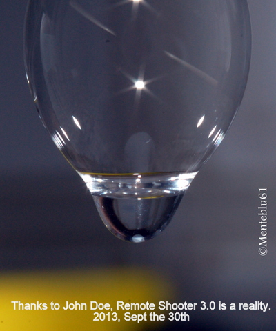
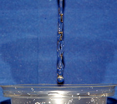
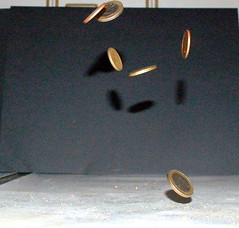
Fare scatti nel mondo della fotografia ad alta velocita’ (caduta di una goccia d’acqua o altro liquido, esplosioni di palloncini etc) o fare scatti a intervalli regolari (anche di molte ore) con la funzione Time Lapse (ad esempio per registrare lo sbocciare di un fiore o lo schiudersi di un uovo) e’ facilmente realizzabile abbinando a questo sistema opportuni sensori di movimento, luce o suono.
Per verificare se la tua fotocamera può essere controllata da RemShoot 1.0 o RemShoot BT 1.0 si consiglia di eseguire il test di compatibilità con l’applicazione per windows (XP e Seven):
http://goo.gl/2BVMg
Una volta effettuato il download estraete il file, lanciate l’eseguibile PTPControlCheck.exe e seguite le istruzioni.
Interessante caratteristica di RemShoot BT 1.0 è che Il firmware è aggiornabile tramite una chiavetta USB.


Se ti interessa Remote Shooter montato e collaudato, completo di display, puoi trovarlo su Ebay Italia (escluso modulo bluetooth)

esempi:


Leggi tutto

giovedì 29 marzo 2012

Remote Shooter 1.0: USB remote control system for cameras


 Modern digital cameras not only use the USB port to transfer images to PC (USB Mass Storage), but also to receive specific control commands that control certain functions (USB PTP). 
 Based on the prototype presented on http://glptech.blogspot.it/2011/12/controlling-digital-camera-via-usb-port.html
 Remote Shooter 1.0 is the complete solution for remote control shooting with Time Lapse functions and events.
Many models of compact and DSLR cameras, Nikon and Canon in particular, are compatible with the USB PIC-AP-BOARD (PIC Auto Programming Board) and the firmware RemShoot 1.0 (Remote Shooter)
 The ability to remotely activate many functions (but especially the shot) on digital cameras give the opportunity of take pictures that sometimes  is manually impossible or at least difficult to achieve with the traditional method because of human reaction times.

NEW:
 tested on:
Nikon Coolpix AW100
Nikon D50
Canon Powershot A300
Canon Poweshot S500

 PTP and applications in photography. 
The PTP commands more interesting to implement for the photo enthusiast are: 
1) Remoting the shutter button (shutter),

2) Interval (Time Lapse) 

3) Set / read values ​​of shutter speed, aperture, etc..

4) Shutter controlled by light sensors and sound reacting to external events
 Making jerky in the world of high speed photography (a falling drop of water or other liquid, explosion of balloons etc) or take shots at regular intervals (even hours) while Time Lapse (eg to record the blossoming of a flower or the hatching of an egg) is easily achieved by combining this system with appropriate sensors, motion, light or sound. 

5) Bracketing (for cameras that provide the function) to make postelaborazioni in HDR. For those not aware, the bracketing feature (usually found on DSLR) cameras in the shows "varied exposure to fork", this includes the performance of at least 3 photos in succession separated by a value of over-and underexposure (longer and shorter than expected) that allows you to "hit" the perfect photo or obtain special software with a special effect (HDR, High Dynamic Range) superimposing the three images. 

The firmware Remshoot 1.0
RemShoot 1.0 handles the shooting of pictures  simultaneously in two different ways:
    1) Through PTP, using the camera's USB connection and remotely shooting.
    2) Using a command pin to safety trigger an external flash. (recommended use of the camera in bulb mode and in darkened environment)

For shots in high speed, as fast, the USB protocol in some cases may not be qualified.
The functions currently available are:
    1) Remoting the shutter button (shutter),

Warning: the remote cord used is that provided for the Generic PTP, used by most compact and DSLR cameras that claim to support the PTP protocol and remote control.

    2) Interval (Time Lapse)
        parameters:

     firing frequency, in seconds
     number of shots

    3) Shutter controlled by light sensors and sound reacting to external events.
        parameters:

     sensor enabled / disabled
     delay in microseconds (necessary in order to synchronize the best shooting with the position of the moving object intercepted by the sensor used)


Compatibility 
To check if your camera can be controlled by RemShoot 1.0 is recommended that you download the application compatibility testing for Windows (XP and Seven):   http://goo.gl/2BVMg

        Fast link
http://goo.gl/2BVMg


Once you have downloaded it,  extract the files, connect your camera to a USB port of your PC (make sure to set PTP mode, NOT Mass Storage Mode), PTPControlCheck.exe run the executable and follow the instructions.

USB PTP 1.0 P&M Lab 2012
The USB PIC-AP-board ready for use, programmed with the firmware RemShoot 1.0.


The philosophy that inspired the PIC-AP-BOARD project:

Invent
: Create your own project

Develop
: Develop and test on-board PIC-AP Board

Use
: complete it and use the same board PIC-AP-Board for your target project.


After several years of testing on development boards more or less evolved (from Microchip products Pic18 to PIC32), we realized that we needed a board of our own and be more self-sufficient as possible, easily powered, equipped with lcd display and keys, and the right number of pin I / O available, first of all capable of selfprogramming without use of external programmers, on which to develop a project more or less complex, which once consolidated revolved on the same board without other passages, but whose firmware be easily updated by anyone.

 
Using the USB PIC-AP-board for various uses

The USB PIC-AP-Board even if they already came with firmware 1.0 RemShoot for controlling a digital camera, can, thanks to its power to function (USB, I2C, SPI, ADC, Timers, PWM, UART, etc.), memory and expandability to be used for purposes other than photography.
The fact sheet can be connected via USB to a PC is powered by independent power supplied from the PC (USB device self-powered or bus powered) thus allowing a wide variety of uses, of course with the right firmware that can be modified by the particular USB boot loader used for updating, thus allowing you to program the card with a simple USB stick with no specific type of programmer for PIC, in each case by the most experienced programmers can also be programmed via ICSP.

To show the great  flexibility of the board we are working to complete other projects that we'll publish for fans of Electronica Open Source Blog, dedicated to the use of graphic displays, or even to connect wireless or wired with PC and Smartphone devices and Android in general, using different categories of sensors or the ability to control external equipment.


Technical specification of USB PIC-AP-BOARD

Schema a blocchi

USB PIC-AP-BOARD : Functional blocks.


The board is built in large part to make it compact SMD (5x7 cm) and easily portable, in addition to the LCD, need to work only 2 AA batteries 1.5 V AA

USB PIC-AP-BOARD
Microcontroller: PIC24FJ256GB106

      1x USB Host / Device (Bus Powered or Self-Powered)
      1x USB MODE jumper
      1x 14-pin LCD connector
      1x 8x2 LCD DISPLAY
      3x Buttons
      16 Input / Output pins and power (5V and 3.3V)
      2x I2C port
      1x serial port
      1x Power LED
      1x ICSP connector for Debug / Program
      Power: 3V with 2 AA batteries 1.5 V
 
The DC-DC converter provides high efficiency at 3.3V and 5V voltages required to power the card, USB devices and any external circuits connected to the expansion connectors

The kit RemShoot 1.0

 For those interested in the solution and tested, ready for use, the kit consists of:

1) Card 1x USB PIC-AP-board mounted, tested and loaded firmware RemShoot1.0 (upgradable)

2) 1x LCD 8x2

3) User Manual supplied with the wiring diagram and pin configuration of port expansion

4) File Gerber board design USB PIC-AP-BOARD

5) File. Hex bootloader USB Adapter-specific for USB PIC-AP-BOARD

6) File. Hex firmware 1.0 RemShoot

Remarkable that with its  USB Host
bootloader, the board can be reprogrammed or updated all through a simple USB key dongle without using any kind of programmers.

For projects we recommend the use of tools like Microchip MPLAB and Microchip C30 compiler, you compile the project, copy the file. Hex on the USB stick once connected to the
PIC-AP-BOARD, program itself in seconds.
Example of a light detector joint with a laser beam


 Shoots remotely controlled by a laser beam


A shoot remotely controlled by a sound trigger


Read more on EMCelettronica Open Source(sorry, is in Italian)

For electronics enthusiasts and DIY Remote Shooter, the project documentation is available at only 9 euros. You can make it yourself (do-it-yourself) by downloading the documentation (schematic, wiring diagram, parts list, assembly plan, gerber files, executable code) from the site  EMCelettronica Open Source.   Download

If you are interested in Remote Shooter assembled and tested, with LCD display, you can find it on Ebay Italy


For every doubt contact me at gianluigi.perrella@gmail.com

mercoledì 21 marzo 2012

Remote Shooter 1.0: sistema di controllo remoto USB per macchine fotografiche


Da diverso tempo le moderne fotocamere digitali possono utilizzare la porta USB non solo per trasferire immagini al PC (USB Mass Storage) , ma anche per ricevere specifici comandi di controllo che ne controllano alcune funzioni (USB PTP). Remote Shooter 1.0 è la soluzione completa per il controllo remoto dello scatto con funzioni di Time Lapse e ad eventi
Molti modelli di compatte e  DSLR, Nikon e Canon in particolare, sono compatibili con la scheda USB PIC-AP-BOARD (PIC Auto Programming Board) ed il firmware RemShoot 1.0 (Remote Shooter)
La possibilità di attivare remotamente molte funzioni (ma in particolare lo scatto) sulle macchine fotografiche digitali rende possibile realizzare fotografie a volte impossibili o almeno difficili da realizzare con il metodo tradizionale a causa dei tempi di reazione umani.

Protocollo PTP e applicazioni nella fotografia.
I  comandi PTP piu’ interessanti da implementare per l’appassionato di fotografia sono:
1) Remotizzazione del pulsante di scatto (shutter),
2) Intervallometro (Time Lapse)
3) Impostazione/lettura dei valori tempi di scatto, apertura diaframma etc.
4) Scatto comandato da sensori di luce e suono in base ad eventi esterni
Fare scatti nel mondo della fotografia ad alta velocita’ (caduta di una goccia d’acqua o altro liquido, esplosioni di palloncini etc) o fare scatti a intervalli regolari (anche di molte ore) con la funzione Time Lapse (ad esempio per registrare lo sbocciare di un fiore o lo schiudersi di un uovo) e’ facilmente realizzabile abbinando a questo sistema opportuni sensori di movimento, luce o suono.
5) Bracketing (per le fotocamere che ne prevedono la funzione) per effettuare postelaborazioni in tecnica HDR. Per chi non fosse a conoscenza, la funzione Bracketing (in genere si trova sulle DSLR) nelle macchine fotografiche indica la "esposizione variata a forcella", questa prevede l'esecuzione di almeno 3 foto in successione separate tra loro da un valore di sovra e sottoesposizione (tempo più lungo e più corto del previsto) che permette di "centrare" la foto perfetta o di ottenere con speciali software un effetto particolare (HDR, High Dynamic Range) sovrapponendo le tre foto.

NEW:
 tested on:
Nikon Coolpix AW100
Nikon D50
Canon Powershot A300
Canon Poweshot S500

Per verificare se la tua fotocamera può essere controllata da RemShoot 1.0 si consiglia di eseguire il test di compatibilità scaricando l’applicazione per windows (XP e Seven):

http://goo.gl/2BVMg

Una volta effettuato il download estraete il file, collegate la vostra macchina fotografica ad una porta USB del vostro PC, (assicuratevi di impostare PTP Mode e non Mass Storage), lanciate l’eseguibile PTPControlCheck.exe e seguite le istruzioni.

La scheda USB PIC-AP-BOARD pronta all'uso, corredata del firmware RemShoot 1.0
USB PTP 1.0 P&M Lab 2012


La filosofia con la quale nasce la PIC-AP-BOARD:

Invent:  Crea il tuo progetto
Develop: Sviluppalo e testalo sulla scheda PIC-AP-BOARD
Use: Completalo e usa la stessa scheda PIC-AP-BOARD per il tuo progetto finito.

Se ti interessa Remote Shooter montato e collaudato, completo di display, puoi trovarlo su Ebay Italia

Leggi tutto su EMCelettronica Open Source


venerdì 23 dicembre 2011

Controlling a digital camera via USB port, now with a Microchip PIC24 family microprocessor


Now with a PIC processor (24 or 32 of the Microchip family) you can control a camera that automatically execute many commands with a system based on a Microchip microcontroller functions with USB Host / OTG embedded.

NEW:
 tested on:
Nikon Coolpix AW100
Nikon D50
Canon Powershot A300
Canon Poweshot S500


The basis of the project 

Always been passionate about photography and electronics, i tried to combine my two hobbies in order to explore new filming techniques and high-speed, with the help of automated systems. The first problem 'was born as camera manufacturers often do not disseminate technical information on the functions of their internal models. Inspired by some of Arduino projects, (particularly that of Alex Glushchenko) and Linux (http://sourceforge.net/projects/libptp/, http://libptp.sourceforge.net/README) after months of work with a friend more skilled than I in C programming, we have designed and built a prototype that implements some USB host control functions of digital cameras via USB PTP protocol, using the embedded functions available on a PIC24F.Compatible between brands and models (PTP functions are not implemented in the same way), we tested some compact DSLR Nikon and Canon. The commands more 'interesting to implement for the photo enthusiast are: 

1) Remoting of the shutter button (shutter) 

2) Set / Read values ​​of shutter speed, aperture, etc.. 

3) Interval (Time Lapse)

4) Remote control of motorized lens focus, depending on the cameras. 

5) Bracket (for cameras that provide the function) to perform post-processing in HDR. For those not aware, the bracketing feature (usually found on DSLR) cameras in the shows "varied exposure bracketing", this includes the performance of at least 3 photos in sequence separated by a value of over-and underexposure (longer and shorter than expected) that allows you to "hit" the perfect photo or obtain a particular effect with special software, HDR (High Dynamic Range) by superimposing the three images (eg HDR). 

The ability to remotely activate many functions (but especially the shot) on digital cameras make possible many photographs sometimes impossible or at least difficult to achieve with the traditional method because of human reaction times.I refer to as jerky in the world of high-speed photography '(fall of a drop of water or other liquid, explosion of balloons, etc.) or techniques of photography on a regular basis (even several hours) as the time-lapse (for example, to record the blossoming of a flower or the hatching of an egg) and 'easily achieved by combining this system with appropriate sensors, motion, light or sound

If you are interested in Remote Shooter assembled and tested, with LCD display, you can find it on Ebay Italy

Description of the prototype and function blocks.


We start with the description of the prototype starting its functional blocks. To work in the field the system must be powered by batteries and consume very little. The first checks the entire system consumes about 90mA with peak and 110mA when 'the backlight of the LCD display (timed and controlled directly from an output pin of the microcontroller).
Now let's see in detail the individual functional blocks:


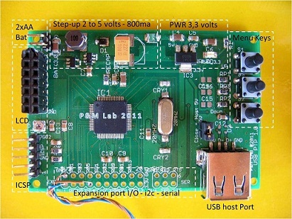
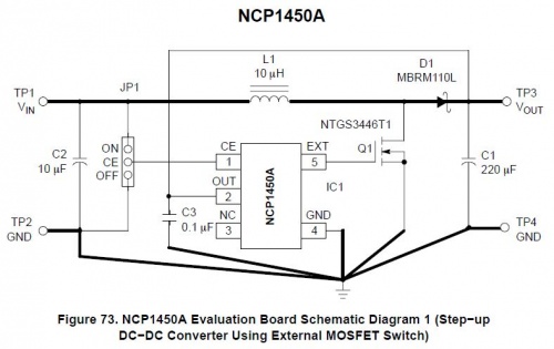
The first block consists of a PWM Step-Up DC-DC converter (NCP1450) with 2 AA batteries, which brings the voltage to 5 volts, with about 800mA max load. The chip 'was chosen because' it is quite efficient (88% max) and can 'work with input voltages from 1.5 to 4.2 volts. Though the CPU and also the LCD display (including backlight) work at 3.3 volts, the voltage to 5 volts is required for USB host functions and to power sensors or external circuits.
Carry the basic layout of the chip that we used in the prototype.


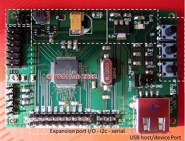
The second block is represented by a classic low dropout regulator (Reg1117) which reduces the voltage to 3.3 volts.Top right we have the three buttons that perform the function of navigation and choose from the menu that appears on the LCD 8x2 (double row connector on the left, with adjacent trimmer contrast).At the center of the PCB we PIC24FJ256GB106 the processor that has a quartz oscillator clock at 20MHz and 72MHz internal PLL configured. For programming and 'was prepared ICSP port (bottom left), as a programmer / debugger use the PICkit2 and 3 with the Microchip MPLAB sw.On the right we find the USB port in Host Configuration and down, centrally located, two rows of connectors for expansion I / O and any communication with sensors / devices or I2C serial (with appropriate external level translators).The prototype had a lot of potential '(the chip and' one of the most powerful and complete PIC24F family with 16Mips power, a lot of memory and 64-pin) can 'be used not only for the purpose for which and' born, but also as a tool development, and 'Simply use the expansion port to connect an analog voltage to be measured or PWM outputs to activate motors etc..Despite some concerns 'Initially, it was' chosen to achieve all or most of the PCB in SMD technology. The questions consisted of mounting a successful prototype SMD having no virtually no previous experience in this technique, and even more 'no technological means as this, and' a hobby for us. In fact the problem 'was brilliantly and in a few minutes, with the technology of the electric cooker at about 210 ° C and the miraculous solder paste that makes everything very simple, the constituent assembly formed in 0805 to 64-TQFP processor pin.Gli any short between pins of the chip during cooking were removed using desoldering braid flux and everything and then tested with the tester.Stages of assemblyThe prototype already 'welded during assembly, ready for the first functional tests (power supplies, buttons, displays etc.)


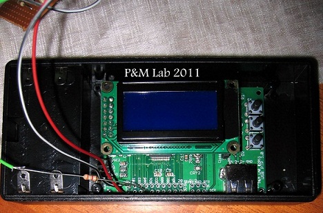
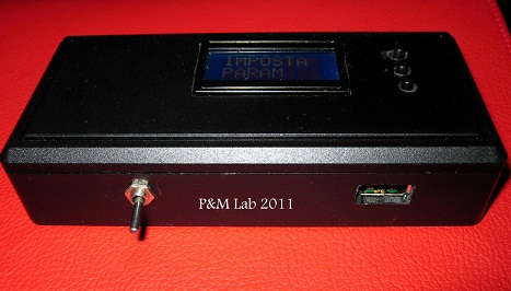
The prototype boxed and ready for the first field tests.


For communication with external sensors we used a DB9F connector which brings out the power supply to 5 volts and some pins of I / O. 

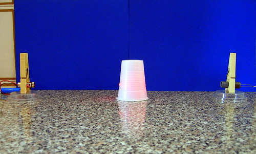
The test image shooting camera when the sensor detects the interruption of the laser beam.

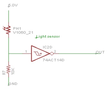
Setup based on a laser pen (left) and LDR (right) with attached Schmitt trigger circuit (with a 74HC14)


Here are some field test to give an idea of the potential with the integration of sensors which pick up sound or light:

Sound Trigger test

Sound Trigger Test


Laser Beam Detector
Laser Beam Detector


Link to some tests made with the prototype:

Test Time Lapse Video
Hi Tech Projects

For contacts mail me at gianluigi.perrella@gmail.com

martedì 22 novembre 2011

Controllare una fotocamera digitale tramite porta USB in modalità PTP 2/2 - Controlling a digital camera via USB port, now with a PIC processor part 2/2


Ora con un processore PIC (famiglia 24 o 32 della Microchip) si può controllare una fotocamera che eseguirà in automatico molti comandi con un sistema basato su un microcontroller della Microchip dotato di funzioni di USB Host/OTG embedded.
Seconda parte: descrizione del prototipo e blocchi funzionali.

Now with a PIC processor (24 or 32 of the Microchip family) you can control a camera that automatically execute many commands with a system based on a Microchip microcontroller functions with USB Host / OTG embedded.

Second part: description of the prototype and function blocks.


Se ti interessa Remote Shooter montato e collaudato, completo di display, puoi trovarlo su Ebay Italia

Leggi tutto / Read More