Visualizzazione post con etichetta dslr. Mostra tutti i post

giovedì 24 maggio 2012

BT Remote Shooter 1.0: Bluetooth Control cameras for Android


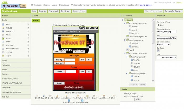
After the completion of Remote Shooter 1.0, the solution for remote control shooting of digital cameras with features Time Lapse and events, we transfer the GUI and its functions on devices using the Android App Inventor.

NEW:
 tested on:
Nikon Coolpix AW100
Nikon D50
Canon Powershot A300
Canon Poweshot S500

The idea stems from the desire to experiment with on Android App Inventor and the practical need to expand the graphic interface of the Remote Shooter 1.0 to make it both easier and faster entry of parameters for Time Lapse or prospective role in the study.
If it is necessary to insert large intervals of time or number of shots, we realized that it could be difficult and perhaps even tedious, use only the up / down on the board.
For those unfamiliar with the project Remote Shooter 1.0, is essentially a sophisticated remote control for remote shooting (but not only) digital camera via USB, in fact, many models of compact and DSLR cameras, Nikon and Canon, for example, are compatible PTP mode with the USB PIC-AP-BOARD (PIC Auto Programming Board) and the firmware RemShoot 1.0 (Remote Shooter).
The ability to remotely activate many functions (first click) on digital cameras, makes it possible to take pictures sometimes impossible or at least difficult to achieve with the traditional method because of human reaction times.
The PTP and applications in photography.
Most digital cameras to provide medium-high level command set PTP for their remote control, or simply to transfer images to a PC.
Using the appropriate commands and properties the photo enthusiast can:
1) remotely the shutter button (shutter),
2) Make an Interval (Time Lapse)
3) Take pictures automatically based on events detected by sensors of light and sound.
Making jerky in the world of high speed photography '(a falling drop of water or other liquid, explosion of balloons etc) or take shots at regular intervals (even hours) while Time Lapse (eg to record the blossoming of a flower or the hatching of an egg) and 'easily achieved by combining this system with appropriate sensors, motion, light or sound.
To check if your camera can be controlled by RemShoot RemShoot BT 1.0 or 1.0 you should run the test compatibility with your application for windows (XP and Seven):
http://goo.gl/2BVMg
Once you extract the download, run the executable and follow the instructions PTPControlCheck.exe.
Interesting feature is that RemShoot BT 1.0 Firmware is upgradeable via a USB stick.

If you are interested in Remote Shooter assembled and tested, with LCD display, you can find it on Ebay Italy (BT Module not included)


examples:

My Portfolio on flickr.com

Read more

lunedì 21 maggio 2012

Remote Shooter BT 1.0: Controllo Bluetooth di macchine fotografiche per Android

main foto2
Dopo la realizzazione di Remote Shooter 1.0, la soluzione per il controllo remoto dello scatto di macchine fotografiche digitali con funzioni di Time Lapse e ad eventi, trasferiamo l'interfaccia grafica e le sue funzioni su dispositivi Android utilizzando App Inventor.

NEW:
Testato su:
Nikon Coolpix  AW100
Nikon D50
Canon Powershot A300
Canon Poweshot S500

L'idea nasce dalla curiosità di sperimentare su Android con App Inventor e dalla necessità pratica di espandere l'interfaccia grafica del Remote Shooter 1.0 per rendere al contempo più semplice e rapido l'inserimento dei parametri di Time Lapse o di future funzioni allo studio.
Nel caso infatti sia necessario inserire grandi intervalli di tempo o numero di scatti, ci siamo resi conto che poteva essere complicato e forse anche tedioso, usare solo i tasti up/down sulla board.
Per chi non conoscesse il progetto Remote Shooter 1.0, è sostanzialmente un sofisticato telecomando per lo scatto remoto (ma non solo) di macchine fotografiche digitali tramite la porta USB, molti modelli infatti di compatte e  DSLR, Nikon e Canon ad esempio, sono compatibili in PTP mode con la scheda USB PIC-AP-BOARD (PIC Auto Programming Board) ed il firmware RemShoot 1.0 (Remote Shooter).
La possibilità di attivare remotamente molte funzioni (prima di tutto lo scatto) sulle macchine fotografiche digitali, rende possibile realizzare fotografie a volte impossibili o almeno difficili da realizzare con il metodo tradizionale a causa dei tempi di reazione umani.
Il protocollo PTP e applicazioni nella fotografia.
Gran parte delle macchine fotografiche digitali di fascia medio alta mettono a disposizione un set di comandi PTP per il loro controllo remoto, o semplicemente per il trasferimento delle immagini su un pc.
Utilizzando gli opportuni comandi e proprietà l’appassionato di fotografia potrà:
1) Remotizzare il pulsante di scatto (shutter),
2) Realizzare un Intervallometro (Time Lapse)
3) Scattare foto automatiche sulla base di eventi rilevati da sensori di luce e suono.
Fare scatti nel mondo della fotografia ad alta velocita’ (caduta di una goccia d’acqua o altro liquido, esplosioni di palloncini etc) o fare scatti a intervalli regolari (anche di molte ore) con la funzione Time Lapse (ad esempio per registrare lo sbocciare di un fiore o lo schiudersi di un uovo) e’ facilmente realizzabile abbinando a questo sistema opportuni sensori di movimento, luce o suono.
Per verificare se la tua fotocamera può essere controllata da RemShoot 1.0 o RemShoot BT 1.0 si consiglia di eseguire il test di compatibilità con l’applicazione per windows (XP e Seven):
http://goo.gl/2BVMg
Una volta effettuato il download estraete il file, lanciate l’eseguibile PTPControlCheck.exe e seguite le istruzioni.
Interessante caratteristica di RemShoot BT 1.0 è che Il firmware è aggiornabile tramite una chiavetta USB.


Se ti interessa Remote Shooter montato e collaudato, completo di display, puoi trovarlo su Ebay Italia (escluso modulo bluetooth)

esempi:


Leggi tutto

venerdì 23 dicembre 2011

Controlling a digital camera via USB port, now with a Microchip PIC24 family microprocessor


Now with a PIC processor (24 or 32 of the Microchip family) you can control a camera that automatically execute many commands with a system based on a Microchip microcontroller functions with USB Host / OTG embedded.

NEW:
 tested on:
Nikon Coolpix AW100
Nikon D50
Canon Powershot A300
Canon Poweshot S500


The basis of the project 

Always been passionate about photography and electronics, i tried to combine my two hobbies in order to explore new filming techniques and high-speed, with the help of automated systems. The first problem 'was born as camera manufacturers often do not disseminate technical information on the functions of their internal models. Inspired by some of Arduino projects, (particularly that of Alex Glushchenko) and Linux (http://sourceforge.net/projects/libptp/, http://libptp.sourceforge.net/README) after months of work with a friend more skilled than I in C programming, we have designed and built a prototype that implements some USB host control functions of digital cameras via USB PTP protocol, using the embedded functions available on a PIC24F.Compatible between brands and models (PTP functions are not implemented in the same way), we tested some compact DSLR Nikon and Canon. The commands more 'interesting to implement for the photo enthusiast are: 

1) Remoting of the shutter button (shutter) 

2) Set / Read values ​​of shutter speed, aperture, etc.. 

3) Interval (Time Lapse)

4) Remote control of motorized lens focus, depending on the cameras. 

5) Bracket (for cameras that provide the function) to perform post-processing in HDR. For those not aware, the bracketing feature (usually found on DSLR) cameras in the shows "varied exposure bracketing", this includes the performance of at least 3 photos in sequence separated by a value of over-and underexposure (longer and shorter than expected) that allows you to "hit" the perfect photo or obtain a particular effect with special software, HDR (High Dynamic Range) by superimposing the three images (eg HDR). 

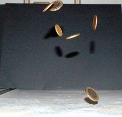
The ability to remotely activate many functions (but especially the shot) on digital cameras make possible many photographs sometimes impossible or at least difficult to achieve with the traditional method because of human reaction times.I refer to as jerky in the world of high-speed photography '(fall of a drop of water or other liquid, explosion of balloons, etc.) or techniques of photography on a regular basis (even several hours) as the time-lapse (for example, to record the blossoming of a flower or the hatching of an egg) and 'easily achieved by combining this system with appropriate sensors, motion, light or sound

If you are interested in Remote Shooter assembled and tested, with LCD display, you can find it on Ebay Italy

Description of the prototype and function blocks.


We start with the description of the prototype starting its functional blocks. To work in the field the system must be powered by batteries and consume very little. The first checks the entire system consumes about 90mA with peak and 110mA when 'the backlight of the LCD display (timed and controlled directly from an output pin of the microcontroller).
Now let's see in detail the individual functional blocks:


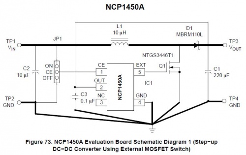
The first block consists of a PWM Step-Up DC-DC converter (NCP1450) with 2 AA batteries, which brings the voltage to 5 volts, with about 800mA max load. The chip 'was chosen because' it is quite efficient (88% max) and can 'work with input voltages from 1.5 to 4.2 volts. Though the CPU and also the LCD display (including backlight) work at 3.3 volts, the voltage to 5 volts is required for USB host functions and to power sensors or external circuits.
Carry the basic layout of the chip that we used in the prototype.


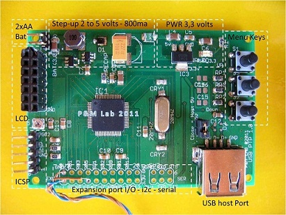
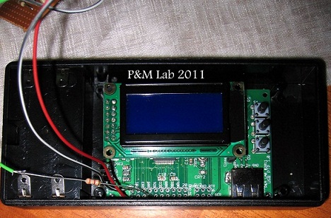
The second block is represented by a classic low dropout regulator (Reg1117) which reduces the voltage to 3.3 volts.Top right we have the three buttons that perform the function of navigation and choose from the menu that appears on the LCD 8x2 (double row connector on the left, with adjacent trimmer contrast).At the center of the PCB we PIC24FJ256GB106 the processor that has a quartz oscillator clock at 20MHz and 72MHz internal PLL configured. For programming and 'was prepared ICSP port (bottom left), as a programmer / debugger use the PICkit2 and 3 with the Microchip MPLAB sw.On the right we find the USB port in Host Configuration and down, centrally located, two rows of connectors for expansion I / O and any communication with sensors / devices or I2C serial (with appropriate external level translators).The prototype had a lot of potential '(the chip and' one of the most powerful and complete PIC24F family with 16Mips power, a lot of memory and 64-pin) can 'be used not only for the purpose for which and' born, but also as a tool development, and 'Simply use the expansion port to connect an analog voltage to be measured or PWM outputs to activate motors etc..Despite some concerns 'Initially, it was' chosen to achieve all or most of the PCB in SMD technology. The questions consisted of mounting a successful prototype SMD having no virtually no previous experience in this technique, and even more 'no technological means as this, and' a hobby for us. In fact the problem 'was brilliantly and in a few minutes, with the technology of the electric cooker at about 210 ° C and the miraculous solder paste that makes everything very simple, the constituent assembly formed in 0805 to 64-TQFP processor pin.Gli any short between pins of the chip during cooking were removed using desoldering braid flux and everything and then tested with the tester.Stages of assemblyThe prototype already 'welded during assembly, ready for the first functional tests (power supplies, buttons, displays etc.)


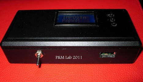
The prototype boxed and ready for the first field tests.


For communication with external sensors we used a DB9F connector which brings out the power supply to 5 volts and some pins of I / O. 

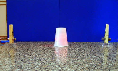
The test image shooting camera when the sensor detects the interruption of the laser beam.

Setup based on a laser pen (left) and LDR (right) with attached Schmitt trigger circuit (with a 74HC14)


Here are some field test to give an idea of the potential with the integration of sensors which pick up sound or light:

Sound Trigger test

Sound Trigger Test


Laser Beam Detector
Laser Beam Detector


Link to some tests made with the prototype:

Test Time Lapse Video
Hi Tech Projects

For contacts mail me at gianluigi.perrella@gmail.com